 ARCHITECTURAL SPECIFICATIONS MODEL 20
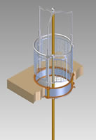
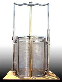
Furnish and install where shown a complete automatic-operating shutter and sliding pole unit constructed with hinged aluminum shutters attached to appendages on ceiling ring. Shutters shall open and close through the medium of connecting cage members that extend through the floor and from a cage with guard rail, guards and self-closing safety gate above the floor. It shall be topped by a tripod suspending the sliding pole which is free to move vertically with the cage actuating the opening and closing of the shutter by the weight of a person sliding down the pole. It shall be of approved type and design manufactured by the McIntire Brass Works, Inc. The hole in the floor shall be framed to suit. All equipment shall be installed in strict accordance with the manufacturer's details.
SLIDE POLES
The poles are available in any length. They are constructed of 2 ½” diameter 5/32” wall cold drawn brass tubing. Purchase of a Model 20 includes both a pole of specified length and a floor flange as well as a 32” diameter landing mat.
We reserve the right to use substitute materials in construction

INSTALLATION
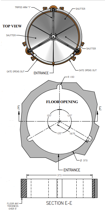
To install the McIntire Automatic Shutter, simply cut or mold a hole in the floor 37 ½” in diameter. At three equi-distant points on a radius of 19 ½”, cut or mold three additional holes each 3" in diameter.
The minimum clearance distances from the center of the sliding pole to any wall or obstruction are: on the cage floor 25" and on the ceiling below and downward 30".
NOTES:
| 1 | IT IS IMPORTANT THAT THE CONTRACTOR LOCATES THE POLE OPENING IN ACCORDANCE WITH THE MINIMUM DISTANCES SHOWN ON THE SHEET |
| 2 | PLAN TO SET THE POLE SO THAT THE ENTRANCE TO THE CAGE WILL BE LOCATED BETWEEN ANY TWO OF THE THREE STANCHIONS. LOCATE THE GATE IN THE MOST PRACTICAL POSTION FOR QUICK ACCESS. |
| 3 | THE FLOOR MUST BE LEVEL. |
| 4 | MINIMUM 5 FLOOR THICKNESS REQUIRED. |
63 Great Road, Unit 108
Maynard, MA 01754
USA.