ARCHITECTURAL SPECIFICATIONS MODEL 21
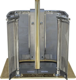
 The Model 21 consists of a steel frame as shown, bronze rails and gate arms surrounding a brass pole that extends from floor to ceiling and stainless steel guarding below the rails and gate arms and two fire-resistant doors. There is a stainless steel electrical enclosure opposite the gate arms that contains a programmable logic controller, an electronic actuator with controller and 2 lights. Two infrared sensors are mounted in the lower front of the electrical enclosure. The sensors send a beam of light across the opening to two reflectors on the gate guards. When either gate is opened, the beam is interrupted and the controller drops the doors. The doors are dropped to the open position as an operator opens the gates. The doors remain in the open position as long as there is a person at floor level on the pole. After a person has slid below the floor level on the pole, the controller waits 20 seconds before closing the doors. If another person slides down the pole during this period the timer is reset and the doors will remain open or drop in mid cycle if need be. See attached drawing for opening specifications. A temperature sensor located on the bottom of the frame will disable the operation of the pole if the temperature below the floor exceeds 180 degrees F.
SLIDE POLES
The poles are available in any length. They are constructed of 2 ½” diameter 5/32” wall cold drawn brass tubing. Purchase of a Model 21 includes both a pole of specified length and a floor and ceiling flange as well as a 32” diameter foam landing mat.
We reserve the right to use substitute materials in construction
INSTALLATION
 The Model 21 requires an opening of 48” by 48”. There should be a minimum of 24” clearance on all sides of the outside of the unit unless permission is given by McIntire Brass Works for a variation. The Model 21 must be connected to a 120 volt AC line on a separate fuse of 15 AMPs as shown in the attached drawing. Use a surge-protected GFI dedicated circuit. McIntire Brass Works, Inc. is not responsible for damage to the electronics inside the electrical enclosure due to voltage spikes or other anomalous power conditions.
The minimum clearance distance from the center of the pole to any wall or obstruction below floor level is 30”.
63 Great Road, Unit 108
Maynard, MA 01754
USA.